
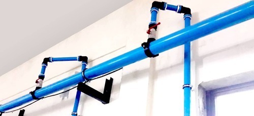
Ccompressed Air Piping System
10000 INR/Piece
Product Details:
- Usage Industrial
- Features Good Quality
- Product Type Compressed Air Piping System
- Material Stainless Steel
- Color Blue
- Warranty 1 year
- Click to view more
X
Ccompressed Air Piping System Price And Quantity
- 10000 INR/Piece
- 1 , , Piece
Ccompressed Air Piping System Product Specifications
- Blue
- Stainless Steel
- Industrial
- 1 year
- Compressed Air Piping System
- Good Quality
Ccompressed Air Piping System Trade Information
- 1 , , Piece Per Day
- 1 Days
Product Description
The purpose of the compressed air piping system is to deliver compressed air to the points of usage. The compressed air needs to be delivered with enough volume, appropriate quality and pressure to properly power the components that use the compressed air. Compressed air is costly to manufacture. A poorly designed compressed air system can increase energy costs, promote equipment failure, reduce production efficiencies, and increase maintenance requirements. It is generally considered true that any additional costs spent improving the compressed air piping system will pay for themselves many times over the life of the system.
Condensate Control
Condensation control must be considered when installing a compressed air piping system. Drip legs should be installed at all low points in the system. A drip leg is an extension of pipe below the airline, which is used to collect condensate in the pipe. At the end of the drip leg a drain trap should be installed. Preferably an automatic drain should be used (see drain valves section of this catalogue for a complete description of the type of drain valves available).
To eliminate oil, condensate, or cooling water (if the water-cooled after cooler leaks), a low point drain should be installed in the discharge pipe before the after cooler. Be sure to connect the after cooler outlet to the separator inlet when connecting the after cooler and the moisture separator together. If they are not connected properly, it will result in either poor aftercooling or poor separation.
The main header pipe in the system should be sloped downward in the direction of the compressed air flow. A general rule of thumb is 1 per 10 feet of pipe. The reason for the slope is to direct the condensation to a low point in the compressed air piping system where it can be collected and removed.
Make sure that the piping following the after cooler slopes downward into the bottom connection of the air receiver. This helps with the condensate drainage, as well as if the water-cooled after cooler develops a water leak internally, it would drain toward the receiver and not the compressor.
Another method of controlling the condensation is to take all branch connections from the top of the airline. This eliminates condensation from entering the branch connection and allows the condensation continue to the low points in the system.
Pressure Drop
Pressure drop in a compressed air system is a critical factor. Pressure drop is caused by friction of the compressed air flowing against the inside of the pipe and through valves, tees, elbows and other components that make up a complete compressed air piping system. Pressure drop can be affected by pipe size, type of pipes used, the number and type of valves, couplings, and bends in the system. Each header or main should be furnished with outlets as close as possible to the point of application. This avoids significant pressure drops through the hose and allows shorter hose lengths to be used. To avoid carryover of condensed moisture to tools, outlets should be taken from the top of the pipeline. Larger pipe sizes, shorter pipe and hose lengths, smooth wall pipe, long radius swept tees, and long radius elbows all help reduce pressure drop within a compressed air piping system.
In recent years we have developed piping systems especially for compressed air. These compressed air piping systems typically have smooth walls, are lightweight, and reduce the installation costs associated with copper and stainless steel piping system.
Loop Pipe System
The layout of the system can also affect the compressed air system. A very efficient compressed air piping system design is a loop design. The loop design allows airflow in two directions to a point of use. This can cut the overall pipe length to a point in half, and that reduces pressure drop. It also means that a large volume user of compressed air in a system may not starve users downstream since they can draw air from another direction. In many cases a balance line is also recommended which provides another source of air.
Reducing the velocity of the airflow through the compressed air piping system is another benefit of the loop design. In cases where there is a large volume user, an auxiliary receiver can be installed. This reduces the velocity, which reduces the friction against the pipe walls and reduces pressure drop. Receivers should be positioned close to the far ends or at points of infrequent heavy use of long distribution lines. Many peak demands for air are short-lived, and storage capacity near these points helps avoid excessive pressure drop and may allow a smaller compressor to be used.
Product details
|
Max work pressure |
13 bar |
|
Usage/Application |
Industrial |
|
I Deal In |
New Only |
|
Compressor Type |
Reciprocating Compressor |
|
Type |
Air Piping |
|
Usage |
Compressed Air |
Tell us about your requirement

Price:
Quantity
Select Unit
- 50
- 100
- 200
- 250
- 500
- 1000+
Additional detail
Mobile number
Email

Other Products in 'Compressed Air Piping System' category

- Plot No. 1562, HSIIDC, Rai Industrial Estate, Distt.- Sonipat,Sonipat - 131029, Haryana, India
- Phone : 08045812855
INTEGRATED ENGINEERS & CONTRACTORS
An ISO 9001 Certified Company
- Mr Puneet Poddar (C.E.O.)
- Mobile : 08045812855
- info@iec.co.in
Contact Info


INTEGRATED ENGINEERS & CONTRACTORS
All Rights Reserved.(Terms of Use)
Developed and Managed by Infocom Network Private Limited.
Developed and Managed by Infocom Network Private Limited.
